Voltage Regulation
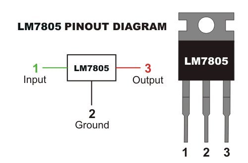
Voltage Regulation is consist of taking an input voltage from either a wall outlet or a battery and regulating it to the desired values. In this case, that means decreasing that voltage to a specified value, depending on the type of regulator that will be used. Based off of researching class D amplifier schematics, the first regulator we researched was the LM78xx series, specifically the LM7805. The 05 on the regulator means whatever input you have that is not above 30V will give you an output of 5V. Same thing goes for the LM7812 which outputs 12V. For our design, we decided that we will get our power from the outlet which going to be 120VAC. Next, an AC to DC converter will be used to output 24V that will be used to power our different amplifier components. Research was also done for the LM393 regulator. With the LM317 regulator, a voltage divider circuit is used to determine the voltage needed. From there we have two methods, either use a power resistor to lower down the voltage to around 15V so there would be decreased heat dissipation when wanting to lower that 15V to 5V using the LM7805 or connect the power supply to the voltage regulators directly, decreasing the voltage from 24V, to 5V and 12V. Since this is a higher voltage drop, a heat sink for the heat that will dissipate from 24V to 5V, and 24V to 12V, might be needed. Heat dissipation will occur on the LM78xx if the input voltage was more than 2-3V from the output. The voltage drop on the LM7812 is lower than the LM7805, so the heat dissipation on is not as much of a concern.
External Power Supply (AC-DC Converter)
For our project, we have decided on using an external power supply. The goal of this power supply is to take the 120VAC from the wall outlet and convert it to 24VDC to be used for our components. This 24V will directly power our mosfets, however, our other components need smaller voltages to operate. We will be using the linear regulators, LM7805, and LM7812.
Using an external power supply will also make our project slightly more flexible. One of the reasons is that if a power malfunction occurs we can replace the power supply without having to open up the amplifier every time. It will also make our amplifier physically smaller.
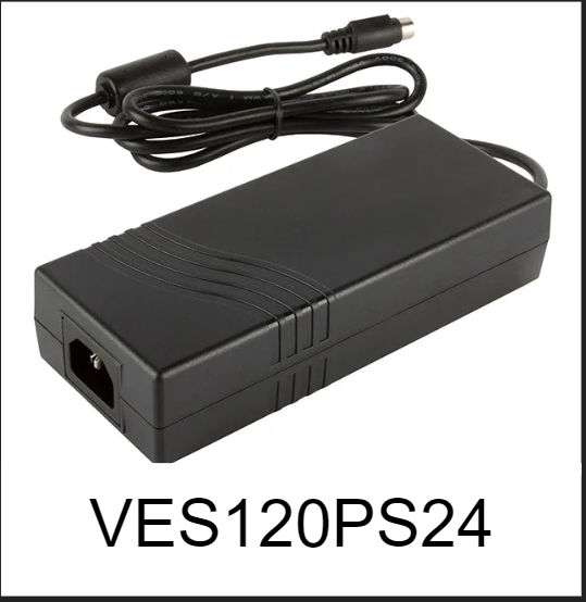
The power supply we have decided on is the XP Power VES120PS24. This is a 24V, 5A power supply. It will supply a power rating of 120W. This power supply is also very efficient, boosting a 89% efficiency. The tradeoff to using an external power supply is that the cost of our amplifier will go up, as external power supplies are generally more expensive than internal counterparts.
Resistor vs Power Resistor
A resistor is a component that is designed to resist the passage of an electric current. In our situation, we considered using a resistor to lower the voltage so that the linear regulator won’t have to dissipate as much heat. What a resistor will do is it will have a voltage drop across it depending on resistance value in Ohms. The higher the resistance the more voltage drop across it the better it is for the linear regulator. To make sure we have the voltage drop we want, we will need to calculate the current, then use Ohm’s Law to calculate the resistance value needed for the desired voltage drop.
Power resistors are designed to withstand and dissipate large amounts of power. In general they have a power rating of at least 3W. Compared to traditional resistors that have a power rating of ¼ – ½. Power resistor seem more efficient because they are made from materials with a high thermal conductivity, allowing efficient cooling. They are designed to be coupled with heat sinks so that way they could handle more power dissipation. In our case, we might have a power dissipation higher than 1W which is why it is beneficial for us to use the power resistance so that it could handle more power dissipation.

Current Calculations
By looking at the datasheets, we were able to find the average current from the power supply to each of our components. Knowing how much current is gonna be driving our ICs is crucial. It allows us to calculate the power loss for the individual components, as well as the power loss of the voltage regulators. This power loss will translate to heat dissipation, and knowing the thermals of our circuit will clarify whether any heatsinks are going to be needed.
Our components, for the most part, are small, plastic chips that might drive high current at certain points. The average current however, is very low. This means that the heat dissipation for most of our components is very small, and thus negligible.
On the other hand, our voltage regulators will have heat dissipation that we will have to compensate for. From our research, power loss is calculated by using this formula:
P = VI
The supply current for each component is compiled in the table below:
| Component | Current | Power Loss | Heat Dissipation |
| TLC555 (timer) | 400uA | 2mW | 25.5°C |
| LM393 (comparator) | 1.00mA | 5mW | 26.5°C |
| IR2113 (gate driver) | 600uA | 6.99mW | 25.7°C |
| LM386 (preamp) | 8.00mA | 40mW | 34.28°C |
| LM7805 (5V regulator) | 9.43mA | 180mW | 35°C |
| LM7812 (12V regulator) | 570uA | 6.84mW | 25.36°C |
| IRLZ44N | 3.5A | 0.5W | 56°C |
From our results, we’ve concluded that our components will not be generating a lot of heat, due to the small amount of current that they draw. This is assuming a 25°C ambient temperature. Our regulators are also well within recommended operating temperatures. Because of our results, we’ve decided that a power resistor will not be necessary to drop the 24V down before our regulating phase.
Switching vs Linear
Difference between linear regulator and switching regulator?
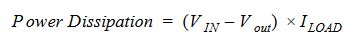
Linear regulators are a great choice for powering very low powered devices or applications where the difference between the input and output is small. Even though they are easy to use, simple and cheap, a linear regulator is normally inefficient. The equation for dissipated power in a linear regulator is:
Furthermore, linear regulators have simple circuit configurations and low noise. That will help give a cleaner signal when outputting to the speakers. The disadvantage of using a linear regulator is that it only has the buck operation. Which means it can only decrease voltage and not increase it. However if used correctly, you would not need to use a switching regulator to increase the voltage. Our LM7805 and LM7812 are being used to decrease the voltage so it can feed our components with 5 and 12 volts as that’s all we need. Our amplifier design does not need boost operation from a voltage regulator. Another disadvantage of a linear regulator is that it generates heat. That is not going to be a big issue though just because to prevent heat dissipation, you need to calculate the power dissipation in order to figure out what heat sink you need to use to prevent the linear regulator of preventing heat.
Switching regulators on the other hand are highly efficient and available as modular chips which are compact and reliable. Switching regulators can be further divided into isolated and non-isolated. They are really useful because they can either work as a buck or a boost regulator. Which basically means that you can increase or decrease the voltage. That would be used for certain types of components. Like sometimes you need to decrease the voltage so it can go through a component and then after it exits that component you increase the voltage so you can input it in the next component. The advantage of a switching regulator is that it will not generate any heat or just minimal heat that can be neglected so you would not need a heat sink. Although, the switching regulator generates noise which will affect the signal when you are going to output it to the speakers and also has a complicated design with more external parts.
Early on, we decided on using a linear regulator. Specifically the LM7805 and LM7812 for 5V and 12V outputs. The reason for that was that the linear regulator is very simple to use and understand. With a switching regulator, we were concerned that its output voltage would have a very large ripple voltage, interfering with our amplifier operations.
One of the switching linear regulators we found was the 78ST1xx model, which has the same pinout as the lm78xx regulators, albeit with a larger footprint. The switching frequency of the 78ST1xx is 600khz-700khz, which is higher than our range for amplifier, which suggests it would be a suitable replacement to our LM78xx regulators. The main reason for it being a potentially better replacement is that switching regulators are very efficient. This means that heat dissipation will not be a problem with the 78ST1xx regulators.
Our advisor, Professor Dorr, however advised us to be more careful. We were informed that since this particular switching regulator does not have an inductor, then the fundamental frequency of the output voltage ripple would be within our frequency range, which could potentially interfere with our circuit and cause noise. Thus, we decided to stick to our first decision with the LM7805 and LM7812 and handle the heat dissipation requirements.