Gate Driver
The IR2113 is a high speed MOSFET driver that accepts low power input and outputs high drive for the gate of a power MOSFET stage. A gate driver is needed for the power output stage in order to minimize crossover distortion. The output stage we are designing requires us to generates minimal crossover distortion while also preventing the power transistors from being turned on simultaneously. Since MOSFETs cannot switch instantaneously they will overlap creating a low impedance connection which would waste power and lead to failure possibly overheat, consequently damaging our transistors and speaker. To avoid this issue the gate driver is used to inject deadtime between the two input PWM signals that will drive the high and low side MOSFETs. The first PWM input signal will be created from the audio signal from the synthesizer compared to the triangle wave, this will be used to drive the high side MOSFET. That PWN will then be inverted and be used as our second input, this inverted PWM signal will be used to drive our low side MOSFET. Propagation delay for both signals are matched to simplify high frequency applications.

https://www.allaboutcircuits.com/projects/how-to-build-a-class-d-power-amplifier/ (picture reference)
Another issue that arises from using a half bridge power MOSFET configuration is that we now require to generate a high bias to drive the high side MOSFET. A bootstrap circuit is used to supply bias to the high side MOSFET. The circuit works by charging a capacitor while the low side MOSFET is conducting and discharging some of the stored voltage to the high side MOSFET through the gate driver.

http://www.ti.com/lit/an/slua887/slua887.pdf (picture reference)
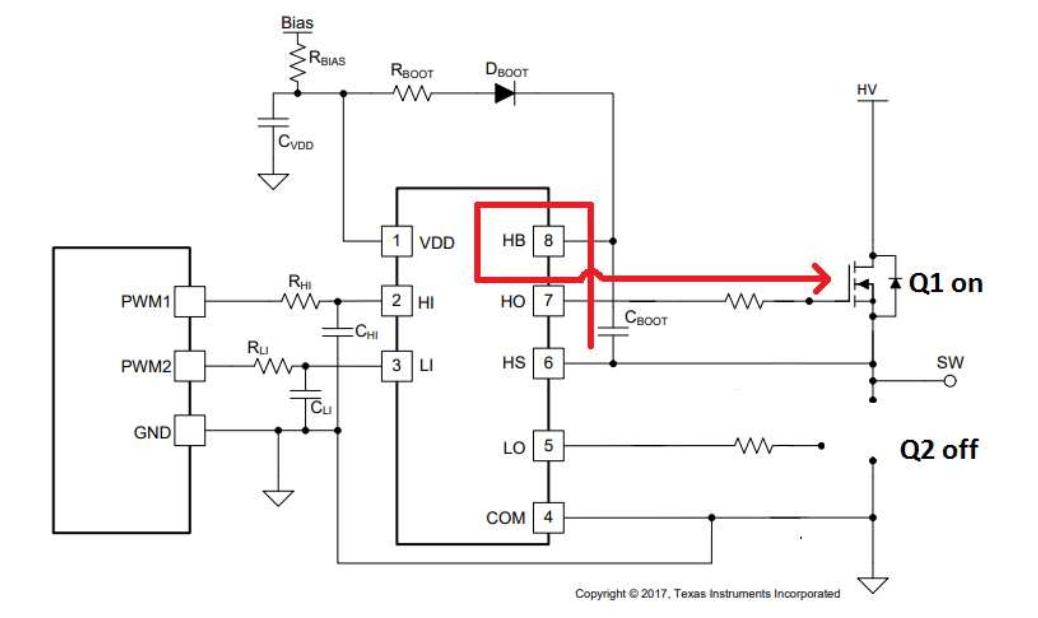
http://www.ti.com/lit/an/slua887/slua887.pdf (picture reference)
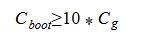
The bootstrap capacitor is commonly designed to be ten times the capacitance of the gate capacitance of the high side MOSFET. The gate capacitance can be determined using the following equation:
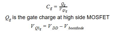
After solving for the gate capacitance, solving for the minimum value of the bootstrap capacitor can be done with the following equation: