Low Pass Filter
The main purpose of the low pass filter is to convert the pulse width modulated signal into an analog signal which is fed into the speakers. The switching frequency of the system is 10 times larger than the audible cutoff frequency in order for the filter to have enough room to reduce the gain of the switching frequency. The filter will have a cutoff frequency of 20kHz due to the audible frequency range for humans being 20-20kHz. The switching frequency of 200 kHz coming from the triangle wave portion of the pulse modulated signal brings unwanted additional frequencies into the signal. The filter produces an analog signal at the output due to the filter attenuating the high switching frequencies of the system. The output of the low pass filter is the 4 speaker.
When designing a low pass filter, a simple passive second order LC circuit would be the best choice. A single pole LC filter will would not be used because of the 20 db/dec roll-off would reduce the cutoff frequency of the filter in order to compensate for attenuating the switching frequencies. The second order LC filter is a simple and effective filter to be implemented into the design. A second order low pass filter would attenuate the 200 kHz switching frequency by 40 dB which would essentially take it out of the system. The filter also does not produce any additional gain to the circuit and has a flat frequency response due to the topology of the circuit.
The filter is the last component before the signal is being fed into the speaker so it is important to pick components that will work best for the project. Plastic film capacitors will be used due to their high voltage capacity and long life. Iron core inductors will be used because they are the standard inductors used for audio equipment.
REFERENCE to be placed at the end:
Inductor:
https://www.electronicshub.org/types-of-inductors-and-applications/
Capacitor
https://www.arrow.com/en/research-and-events/articles/using-capacitors-to-filter-electrical-noise
https://www.electrocube.com/details/capacitors-in-audio-crossover-networks/
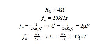
Hand Calculations:
LTSpice Schematic:

LTSpice Bode Plot:

The spice simulation verifies that the cutoff frequency is at 20kHz and at 200kHz the signal is attenuated by 40dB.