Preamp
The preamp is the first stage of the audio amplifier in which it amplifies the input audio signal with as little distortion as possible. The preamp will be used to test our amplifier with multiple low level external audio sources like a guitar or phone. Since we are designing our amplifier to be compatible with the Spacetrip: Synthesizer project we need to be able to experiment with other devices because their synthesizer may not be ready. This helps in with the troubleshooting and redesign phase of the project since we don’t have to wait for the Synthesizer team to be completely finished to see how the amplifier sounds.
A preamp is needed for the amplifier in order to filter out the added noise interference from the transmission line cables coming from the external audio source. The preamp also gives the user the option of changing the input gain of the signal which controls the volume of the amplifier.The preamp is an important part of the audio amplifier because any added noise in the first stage will be amplified at the output stage. The output signal from the preamp is fed into the comparator integrated circuit which will be used to create a pulse width modulated signal of the preamp audio signal. An external preamp could have been used, however implementing a built-in preamp would make our project an all-in-one audio amplifier.
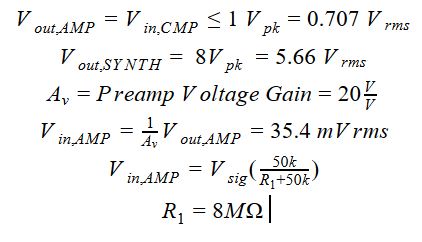
When designing the preamp, our requirement was that the preamp would amplify low voltage signals with low Total Harmonic Distortion. The designing process started by working backwards from the output voltage to designing the voltage divider to bias the input voltage. Since the output of the preamp signal is being fed into the input of the comparator, the output voltage of the preamp needs to be within the rated input voltage of the comparator. The gain of the preamp is set to a specific gain where the input voltage needed could be found by working backwards. The voltage divider needs to be added to the beginning of the preamp in order to bias the preamp at the correct voltage and to stay within our specifications. The input connection that will be used is a ¼ inch input jack because this is commonly used for audio source connections.
The chip that was researched and implemented into the design was the LM386 integrated circuit. The LM386 has a voltage gain that can be set between 20 and 200 VV but the current designs use a fixed gain of 20. The input voltage ranges form -0.4V and 0.4V and a Total Harmonic Distortion rated at 0.2%.
Specifications:
IC: LM386
- Input Voltage: -0.4 to 0.4 V
- Voltage Supply: 4 to 12 V
- Gain: 20 to 200 VV
- Total Harmonic Distortion (THD): 0.2%
Input Connection:
- ¼ inch Input Jack
Expected Output Voltage from Synthesizer:Vout,SYNTH=8 Vpk=5.66 Vrms
Output Voltage:

LM386 Schematic and Pin Configuration:


Hand Calculations: